(Beamforming code download: https://github.com/JiaoXianjun/sdrfun)
Since the double-slit interference pattern can be moved by altering the light delay in one of the slits, you must have realized that if we can control the delay/phase of the radio signal before it leaves the antenna, we might be able to direct the beam where we want it. Indeed, this is the basic principle of beamforming. By applying delay/phase to the signal per antenna, we can shape the beam as desired. Next, let’s start from a simple case: applying phases of 0 and π to the the two rod antennas in the previous article. Run the following command:
python3 -c "from beamforminglib import *; ant_array_beam_pattern(freq_hz=2450e6, array_style='linear', num_ant=2, ant_spacing_wavelength=0.5, beamforming_vec_rad=np.array([0, np.pi]))"
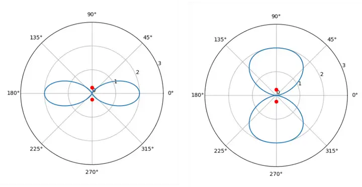
The figure on the right is obtained by the above command, with the left showing the original beam.
Similar to the double-slit interference case, in this case, there is no signal at 0 degrees (to the right).
Since the beam can be directed towards 0 and 90 degrees by applying phases (0 and π) to the two antennas, wouldn’t it be possible to do beam scanning by using some intermediate phase values? The answer is YES. The following command demonstrates beam scanning by continuously changing the phase of the 2nd antenna from -π to π with step size π/8 while keeping the phase of the 1st antenna 0:
python3 test_linear2_bf_scan.py
If you open the test_linear2_bf_scan.py, you will find: it calls the same python function ant_array_beam_pattern continuously and gives a series of phase (-π to π with step size π/8) to the 2nd antenna via the 2nd element of the argument beamforming_vec_rad, which are listed in the following table:
| time | phase ant0 | phase ant1 |
|---|---|---|
| 0 | 0 | -π |
| 1 | 0 | -7π/8 |
| 2 | 0 | -6π/8 |
| 3 | 0 | -5π/8 |
| 4 | 0 | -4π/8 |
| 5 | 0 | -3π/8 |
| 6 | 0 | -2π/8 |
| 7 | 0 | -1π/8 |
| 8 | 0 | 0 |
| 9 | 0 | 1π/8 |
| 10 | 0 | 2π/8 |
| 11 | 0 | 3π/8 |
| 12 | 0 | 4π/8 |
| 13 | 0 | 5π/8 |
| 14 | 0 | 6π/8 |
| 15 | 0 | 7π/8 |
To generate a narrower beam and the scanning, the number of antennas in the array can be extended from 2 to 8. The antenna spacing is still half of the wavelength. All antennas are in one line. This kind of array topology is called ULA: Uniform Linear Array. Regarding the phasing scheme: the 1st antenna’s phase is kept 0, and starting from the 2nd antenna the phasing step sizes are π/8, 2π/8, 3π/8, …, 7π/8. You can check test_linear8_bf_scan.py to see the exact beamforming phase vector with 8 elements (argument beamforming_vec_rad). The corresponding command and scanning figure are:
python3 test_linear8_bf_scan.py
The corresponding phases per antenna are:
| time | ant0 | ant1 | ant2 | ant3 | ant4 | ant5 | ant6 | ant7 |
|---|---|---|---|---|---|---|---|---|
| 0 | 0 | -π | -2π | -3π | … | … | … | -7π |
| 1 | 0 | -7π/8 | -2*7π/8 | -3*7π/8 | … | … | … | -7*7π/8 |
| 2 | 0 | -6π/8 | -2*6π/8 | -3*6π/8 | … | … | … | -7*6π/8 |
| 3 | 0 | -5π/8 | -2*5π/8 | -3*5π/8 | … | … | … | -7*5π/8 |
| 4 | 0 | -4π/8 | -2*4π/8 | -3*4π/8 | … | … | … | -7*4π/8 |
| 5 | 0 | -3π/8 | -2*3π/8 | -3*3π/8 | … | … | … | -7*3π/8 |
| 6 | 0 | -2π/8 | -2*2π/8 | -3*2π/8 | … | … | … | -7*2π/8 |
| 7 | 0 | -1π/8 | -2*1π/8 | -3*1π/8 | … | … | … | -7*1π/8 |
| 8 | 0 | 0 | 0 | 0 | 0 | 0 | 0 | 0 |
| 9 | 0 | 1π/8 | 2*1π/8 | 3*1π/8 | … | … | … | 7*1π/8 |
| 10 | 0 | 2π/8 | 2*2π/8 | 3*2π/8 | … | … | … | 7*2π/8 |
| 11 | 0 | 3π/8 | 2*3π/8 | 3*3π/8 | … | … | … | 7*3π/8 |
| 12 | 0 | 4π/8 | 2*4π/8 | 3*4π/8 | … | … | … | 7*4π/8 |
| 13 | 0 | 5π/8 | 2*5π/8 | 3*5π/8 | … | … | … | 7*5π/8 |
| 14 | 0 | 6π/8 | 2*6π/8 | 3*6π/8 | … | … | … | 7*6π/8 |
| 15 | 0 | 7π/8 | 2*7π/8 | 3*7π/8 | … | … | … | 7*7π/8 |
(To be continued …)